

The Seed3 Desktop Dev Kit is the ultimate Daisy-powered prototyping platform for synths, samplers, and effects. Built around the Seed3, it gives you everything you need to design powerful polysynths, sequenced samplers, and rich DSP effects — all on the same hardware.
With essential audio, MIDI, CV, and control components at your fingertips, the Desktop Dev Kit makes it easy to bring your ideas to life. From stereo audio I/O to hands-on knobs and switches, it's packed with the tools you need to shape your next instrument or effect. Add USB-C connectivity, a microSD card slot, and a dedicated headphone amp, and you've got a ready-made studio workbench for turning concepts into commercial products.
- Features
- Specifications
- Getting Started
- Making Your Own Project
- Hardware Reference
- Resources & Support
- Open-Source Hardware
- License
| Category | Details |
|---|---|
| Audio | Stereo line-level input and output, with input jack detection |
| Headphones | 3.5mm headphone output with volume control |
| MIDI | DIN MIDI In, Out, and Thru |
| CV & Gate | 2 × CV inputs, 2 × gate inputs, 2 × CV outputs |
| USB | USB-C port for power, programming (with the Daisy bootloader), and USB serial |
| Storage | microSD slot (with card detect) for firmware updates, samples, presets, configuration, and more |
| Potentiometers | 8 × 10kΩ linear (B-taper) |
| Buttons | 16 × tactile switches, each with an LED |
| Toggle Switches | 2 × toggle switches (1 × ON-OFF-ON, 1 × ON-ON) |
| Parameter | Value |
|---|---|
| Processor module | Daisy Seed3 |
| Power | +5V via the Dev Kit's USB-C port |
| Current draw | Firmware dependent |
| Audio codec / sample rate | TAC5242 / up to 32-bit, 192kHz |
| Input impedance | 20kΩ |
| Output impedance | 100Ω |
| CV input range | -5V to +5V |
| CV output range | 0V to +5V |
| Gate input threshold | +0.4V |
| Board dimensions | 197mm × 111mm |
| MIDI connectors | 3 × 5-pin DIN (In, Out, Thru) |
Important
This kit has two USB-C ports: one on the Dev Kit board (J7, above the Seed3) and one on the Seed3 module itself. The steps below say which one to use. Day-to-day, you power, program, and monitor the Dev Kit through the board's USB-C port.
Follow the Daisy C++ Getting Started guide. It installs the toolchain and clones DaisyExamples, which includes libDaisy (hardware library) and DaisySP (DSP library).
The Desktop Dev Kit template and board support are newer than the copy of libDaisy included with DaisyExamples. From your DaisyExamples folder, update libDaisy to its latest version, fetch its own dependencies, and rebuild it:
git submodule update --remote libDaisy
git -C libDaisy submodule update --init --recursive
make -C libDaisy
The first line moves libDaisy to its latest version. The second fetches libDaisy's own dependencies, such as the STM32 drivers it needs to compile. The last line rebuilds libDaisy, which is required after any update.
Caution
Running git submodule update --init --recursive or git pull --recurse-submodules from the DaisyExamples folder afterwards resets libDaisy to the older version DaisyExamples was built with. If that happens, run the three commands above again.
The starting project for this kit is examples/devkits/Desktop-DevKit-UI-Template. It reads every input on the Dev Kit, manages the 16 buttons, 8 pots, and LEDs with libDaisy's UI class, and prints input changes over USB serial. From the libDaisy folder:
cd examples/devkits/Desktop-DevKit-UI-Template
make
This creates Desktop-DevKit-UI-Template.bin in the template's build/ folder.
The template runs from the Daisy bootloader, using the variant that accepts new programs over the Dev Kit's USB-C port. You install the bootloader once, through the Seed3's USB-C port:
-
Connect a USB-C cable from your computer to the USB-C port on the Seed3 module.
-
Hold BOOT, press and release RESET, then release BOOT.
-
From the template folder, run:
make program-boot
Or choose the v6.x (external) bootloader in the Daisy Web Programmer.
You don't need to reinstall the bootloader unless you switch bootloader variants, or want to program an app to the Seed3's internal flash.
-
Move the USB-C cable to the Dev Kit's USB-C port (J7, above the Seed3). This port also powers the board.
-
Press RESET, then BOOT on the Seed3. The Seed3's USR LED blinks quickly, then pulses slowly, which means it's ready to receive a program.
-
From the template folder, run:
make program-dfu
Or, in the Daisy Web Programmer, upload the
Desktop-DevKit-UI-Template.binfile from thebuild/folder.
Once flashed, the Seed3's USR LED blinks at a steady rate, and:
- Pressing a tactile switch lights its LED.
- CV Out 1 and CV Out 2 output a slow ramp and a saw wave.
- MIDI notes sent to MIDI In are echoed to MIDI Out.
- Audio at the inputs passes straight through to the outputs and the headphone jack.
- A serial monitor connected to the Dev Kit's USB-C port shows a message whenever any input changes.
Edits only take effect on the Dev Kit after you rebuild and reflash, so start your own project from a copy of the template.
-
Copy the
Desktop-DevKit-UI-Templatefolder into yourDaisyExamplesfolder and rename it, for exampleDaisyExamples/MyInstrument. -
In the copied
Makefile:- Set
TARGETto your project name, for exampleTARGET = MyInstrument. - Change
LIBDAISY_DIRto point to libDaisy from the new location:LIBDAISY_DIR = ../libDaisy. - To use DaisySP, uncomment the DaisySP line and set
DAISYSP_DIR = ../DaisySP. - Keep the
APP_TYPE=BOOT_SRAMandBOOT_BINlines. They make your program run from the bootloader you installed in step 4.
- Set
-
Write your instrument in
src/main.cpp, and adjust the button and pot handling insrc/main_page.h. Audio is processed inAudioCallback(): inputs arein[0][i](left) andin[1][i](right), and outputs areout[0][i]andout[1][i](see Audio). -
Rebuild and flash after every change, using the Dev Kit's USB-C port:
make
make program-dfu
Press RESET, then BOOT, before each
make program-dfu.
Tip
The template builds with debugging enabled (DEBUG = 1, OPT = -Og). For release builds, set DEBUG = 0 and OPT = -O3 in the Makefile.
The Ref column lists each part's reference designator, as printed on the board's silkscreen.
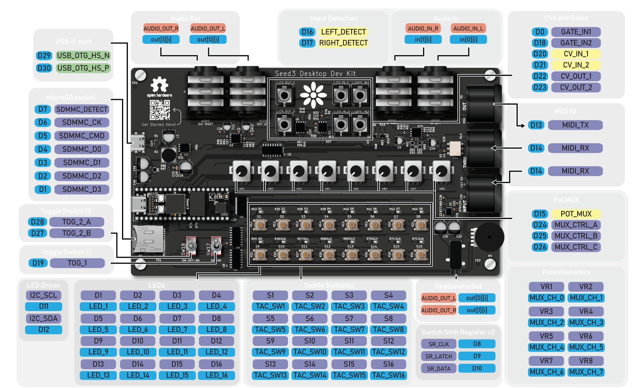
A printable Pinout PDF is also available.
| Jack | Ref | Signal | Audio Callback |
|---|---|---|---|
| Input Left | J1 | AUDIO_IN_L |
in[0][i] |
| Input Right | J2 | AUDIO_IN_R |
in[1][i] |
| Output Left | J3 | AUDIO_OUT_L |
out[0][i] |
| Output Right | J4 | AUDIO_OUT_R |
out[1][i] |
| Headphones | J5 | AUDIO_OUT_L / AUDIO_OUT_R |
out[0][i] / out[1][i] (mirrors the main outputs) |
| Headphone volume | RV1 | — | Analog volume control, not read by the Seed3 |
| Jack | Ref | Signal | Seed3 Pin |
|---|---|---|---|
| Input Left | J1 | LEFT_DETECT |
D16 |
| Input Right | J2 | RIGHT_DETECT |
D17 |
The eight pots are read through a single ADC pin via an 8-channel analog multiplexer (U12). Set the select lines A/B/C to choose a channel, then read POT_MUX.
| Signal | Seed3 Pin |
|---|---|
POT_MUX (ADC) |
D15 |
MUX_CTRL_A |
D24 |
MUX_CTRL_B |
D25 |
MUX_CTRL_C |
D26 |
| Pot | Ref | Mux Channel |
|---|---|---|
| Potentiometer 1 | VR1 | MUX_CH_0 |
| Potentiometer 2 | VR2 | MUX_CH_1 |
| Potentiometer 3 | VR3 | MUX_CH_2 |
| Potentiometer 4 | VR4 | MUX_CH_3 |
| Potentiometer 5 | VR5 | MUX_CH_4 |
| Potentiometer 6 | VR6 | MUX_CH_5 |
| Potentiometer 7 | VR7 | MUX_CH_6 |
| Potentiometer 8 | VR8 | MUX_CH_7 |
The 16 tactile switches are read through two daisy-chained shift registers (U4, U5).
| Signal | Seed3 Pin |
|---|---|
SR_LATCH |
D9 |
SR_CLK |
D8 |
SR_DATA |
D10 |
Switches S1–S16 map to TAC_SW1–TAC_SW16, arranged in two rows of eight:
| S1 | S2 | S3 | S4 | S5 | S6 | S7 | S8 |
| S9 | S10 | S11 | S12 | S13 | S14 | S15 | S16 |
The 16 LEDs (LED_1–LED_16, refs D1–D16) sit in the same two rows of eight as the tactile switches, each LED just above its switch (D1 above S1, through D16 above S16), and are driven by a PCA9685 LED driver (U8) over I²C.
| Signal | Seed3 Pin |
|---|---|
I2C_SCL |
D11 |
I2C_SDA |
D12 |
Note
LED refs D1–D16 are component reference designators, not Seed3 pins.
| Switch | Ref | Signal | Seed3 Pin | Type |
|---|---|---|---|---|
| Toggle switch 1 | SW17 | TOG_1 |
D19 | ON-ON |
| Toggle switch 2 | SW18 | TOG_2_A / TOG_2_B |
D28 / D27 | ON-OFF-ON (3-position, two pins) |
| Jack | Ref | Signal | Seed3 Pin |
|---|---|---|---|
| Gate In 1 | J_GATE_IN1 | GATE_IN1 |
D0 |
| Gate In 2 | J_GATE_IN2 | GATE_IN2 |
D18 |
| CV In 1 | J_CV_IN_1 | CV_IN_1 |
D20 |
| CV In 2 | J_CV_IN_2 | CV_IN_2 |
D21 |
| CV Out 1 | J_CV_OUT_1 | CV_OUT_1 |
D23 (DAC channel 1) |
| CV Out 2 | J_CV_OUT_2 | CV_OUT_2 |
D22 (DAC channel 2) |
| Jack | Ref | Signal | Seed3 Pin | Direction |
|---|---|---|---|---|
| MIDI Out | J11 | MIDI_TX |
D13 | Out |
| MIDI In | J10 | MIDI_RX |
D14 | In |
| MIDI Thru | J8 | MIDI_RX |
D14 | Mirrors MIDI In |
| Signal | Seed3 Pin |
|---|---|
SDMMC_CK |
D6 |
SDMMC_CMD |
D5 |
SDMMC_D0 |
D4 |
SDMMC_D1 |
D3 |
SDMMC_D2 |
D2 |
SDMMC_D3 |
D1 |
SDMMC_DETECT |
D7 |
The Dev Kit's USB-C port (J7) powers the board and connects to the Seed3's external USB peripheral. It is separate from the USB-C port on the Seed3 module.
| Signal | Seed3 Pin |
|---|---|
USB_OTG_HS_N |
D29 |
USB_OTG_HS_P |
D30 |
- Product Page: Seed3 Desktop Dev Kit
- Documentation: docs.daisy.audio
- Community Forum: community.daisy.audio
- Discord: Daisy Discord
- Issues: Report bugs or hardware errata via this repository's Issues tab.

The Desktop Dev Kit is open-source hardware, built to the Open Source Hardware Definition published by the Open Source Hardware Association (OSHWA). The schematics, PCB layouts, bill of materials, and KiCad source files are published so that you can study, modify, manufacture, and sell your own designs based on them.
Copyright © 2026 Qu-Bit Electronix, Inc. (dba Daisy)
The hardware design files in this repository are licensed under the CERN Open Hardware Licence Version 2 – Permissive (CERN-OHL-P-2.0).
Subject to the terms of that licence, you may:
- Use, study, copy, modify, and distribute these designs and any products made from them.
- Incorporate these designs, in whole or in part, into closed-source and commercial products.
These designs are provided "as is", without warranty of any kind, express or implied. See LICENSE for the full licence text, including the disclaimer of warranty and limitation of liability.
Firmware and software, including libDaisy and DaisySP, are licensed separately under the terms included in their respective repositories.
SPDX-License-Identifier: CERN-OHL-P-2.0
DAISY® is a trademark of Qu-Bit Electronix, Inc., registered in the United States. CERN-OHL-P-2.0 grants a license to the copyright and related rights in these designs. It does not grant any right or license to use the DAISY name, logos, product names, or other trademarks of Qu-Bit Electronix, Inc.
Products, derivative designs, and related materials made from these designs may not:
- Use the DAISY name or logo, or any confusingly similar name or mark, in a product name, model number, brand, domain name, or marketing material.
- Reproduce the DAISY name or logo on a PCB silkscreen, front panel, enclosure, packaging, or documentation, except where needed to keep the required licence notices.
- State or imply that the product is made, endorsed, sponsored, certified, or supported by Qu-Bit Electronix, Inc.
You may make truthful, factual statements about compatibility or origin, such as "based on the Seed3 Desktop Dev Kit design" or "compatible with the Daisy Seed3", provided the statement does not suggest affiliation or endorsement. If you redistribute or sell products derived from these designs, remove the DAISY name and logo from the silkscreen and other artwork before manufacture.
For trademark licensing or permission requests, contact Qu-Bit Electronix, Inc. through daisy.audio/pages/support.