

|

|
WIKI/HELP in German and English
PSXKEY is a very small program (resident driver - TSR) for MS-DOS that reads a PlayStation (PSX/PS1/PS2) controller through the parallel (LPT) port and injects the mapped buttons as keyboard keystrokes. This lets you play DOS games with a PSX gamepad.
Originally built and tested on an IBM ThinkPad 380XD and Toshiba Satellite Pro 4600 running MS-DOS (Windows 98 DOS, boot mode XMC = HIMEM only). EMM386 works as well (tested on a Toshiba Satellite Pro 4300 with Project X, which needs EMS). It does not run in a Windows DOS box, where the port I/O is virtualized.
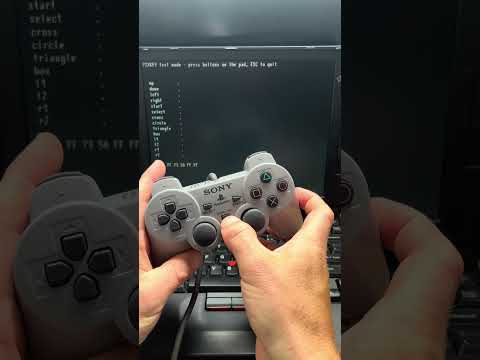
Simply copy psxkey onto your hdd of the DOS PC and execute it. It then runs in the background and converts the controller inputs into keyboard inputs. I think every game is supported (if not please create a issue). As well as the program, you’ll also need an LPT-to-PSX adapter. You can either build one yourself or buy one from me (see below).
Details:
Keys are injected at the INT 9 / KBC level using keyboard-controller command 0xD2,
not into the BIOS keyboard buffer (INT 16h). This is what makes it work with games that
read the keyboard hardware directly (port 0x60 / their own INT 9 handler), such as
King's Chase (Timegate) and Commander Keen. Plain BIOS-buffer injection was not
enough for those titles.
| Command | Action |
|---|---|
PSXKEY |
Install the driver (reads PSXKEY.INI). |
PSXKEY /U |
Unload the driver. |
PSXKEY /? |
Show help (commands, INI options, buttons and keys). |
PSXKEY /T |
Test mode: show all buttons live, without installing. |
Note: Double-loading is prevented via an INT 2Fh multiplex ID (0xC9). Unloading restores INT 8
and INT 2Fh and frees the memory; it reports "cannot unload" if another TSR was loaded
after PSXKEY (since the interrupt chain can no longer be safely unhooked).
The driver prints its banner, the full path of the INI it loaded and that file's contents, so you can see at a glance which configuration is actually in effect:
PSXKEY PSX Controller Driver for LPT and MS-DOS by ottelo (ottelo.jimdofree.com)
build 26-09-01 12:24   github.com/ottelo9
ini: C:\TOOLS\PSXKEY.INI
[psx]
port = auto
box = a
cross = x
...
port: 0x0378
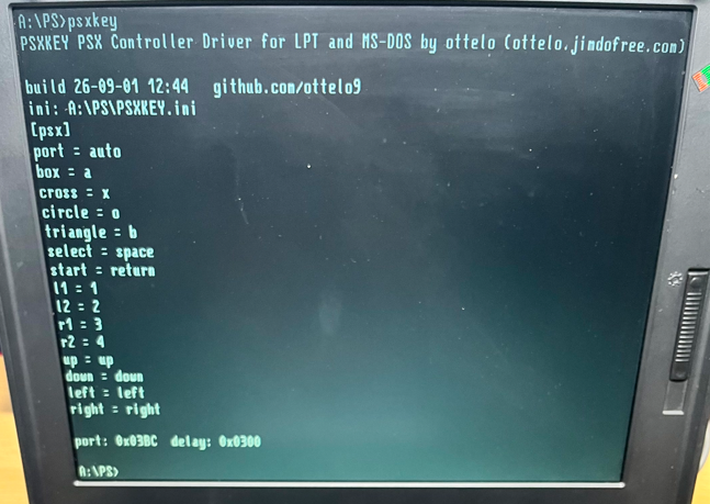
The listing is dumped from the same buffer the parser reads, so it shows what the driver
really saw — not a separate copy. The last line is the LPT port the driver ended up
using, which is what you want to see when port = auto is in effect. If no INI was found,
psxkey: PSXKEY.INI not found - created default. is printed first, followed by the path
and contents of the file that was just created.
PSXKEY /T checks the adapter and the pad without installing anything. It clears the
screen, lists the 14 buttons and marks each one * while it is held and . while it is
not. The five raw response bytes are shown underneath, so you can tell a wiring fault from
a mapping problem. ESC quits and restores the screen.
PSXKEY test mode - press buttons on the pad, ESC to quit

  up          .
  down        *
  left        .
  ...

  raw: FF 41 5A FF DF
  polls: 01A3  errors: 0000
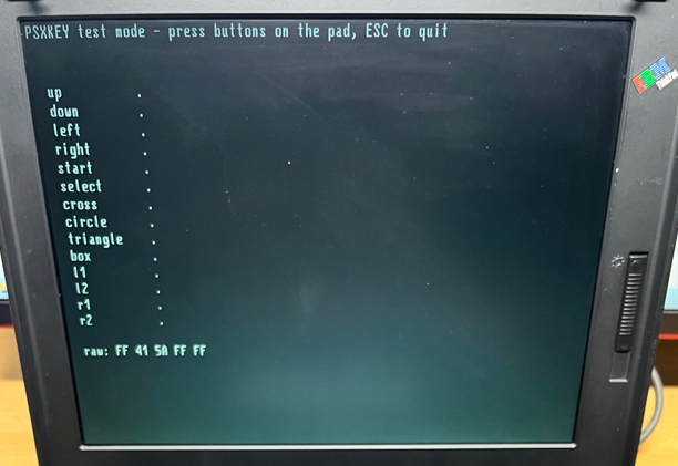
Test mode runs before the interrupts are hooked, but after the INI has been read, so
port = auto and delay apply here as well. It refuses to run while PSXKEY is already
resident — the installed copy polls the same port from the timer interrupt and the two
would corrupt each other's transfers. Unload with /U first.
The last line counts the polls and the faulty responses (both hex). Test mode polls once
per timer tick (18.2 Hz), the same rate as the resident driver; polling back to back is
too fast for many pads and produces errors that never occur in normal use. A response counts as
faulty when the third byte is not 5A. The resident driver ignores such responses and
keeps the previous button state; without that, a single bad poll looks like "all buttons
released" and the game sees the key flicker (seen in The Lion King with timer = rtc).
If errors keeps rising, try a larger delay (test option, see below).

I’m selling a ready-2-use adapter/converter that I designed and built myself. You can buy it on eBayaffiliate link or contact me. Your purchase supports my work :) .
The adapter is powered from the parallel port's data pins through 4 diodes, which yields only a few milliamps and supply the controller from a 3.3 V LDO. The three lines "CLK, CMD and ATT" go through a level shifter that runs off that same rail. So nothing the adapter actively drives can exceed 3.3 V. Current draw is likely the real limit. If you have problems with the adapter e.g. if you want to use a wireless receiver that draws more than a wired pad you can supply the converter with 5V via the 2-pin header. The LDO still regulates it down to a clean 3.3 V, and the diodes block any back-feed into the port.
The INI file has the same base name as the COM and is located via the PSP environment path. If it is missing, a default INI is created automatically. Both the path and the contents of the INI in effect are printed at startup.
- Line format:
button = key. - Lines starting with
[,;, or//are ignored. port = 0x3BC(orlpt = ...) sets the LPT port (hex,0xoptional).port = autoprobes for the controller automatically (see below). This is the default in the generated INI.delay = 0x300(test option) forces the bit-bang delay loop count (hex) and skips the automatic timing search. Not needed in normal use,port = autofinds the value itself.timer = rtcpolls the pad from the real-time clock interrupt instead of the system timer (see below).
Buttons: up down left right start select cross circle triangle box l1 l2 r1 r2
Keys (complete list; names are case-insensitive, scancodes are set 1):
| INI value | Key | Scancode |
|---|---|---|
a … z |
letters | 1E 30 2E 20 12 21 22 23 17 24 25 26 32 31 18 19 10 13 1F 14 16 2F 11 2D 15 2C |
1 … 9, 0 |
number row | 02 … 0A, 0B |
space |
Space | 39 |
return, enter |
Enter (main) | 1C |
esc |
Esc | 01 |
tab |
Tab | 0F |
backspace |
Backspace | 0E |
f1 … f10 |
function keys | 3B … 44 |
f11, f12 |
function keys | 57, 58 |
up down left right |
cursor keys | E0 48, E0 50, E0 4B, E0 4D |
ctrl |
left Ctrl | 1D |
alt |
left Alt | 38 |
shift |
left Shift | 2A |
num0 … num9 |
numpad digits | 52 4F 50 51 4B 4C 4D 47 48 49 |
num. |
numpad . / Del |
53 |
num+ |
numpad + |
4E |
num- |
numpad - |
4A |
num* |
numpad * |
37 |
num/ |
numpad / |
E0 35 |
numenter |
numpad Enter | E0 1C |
Letters are physical key positions (US layout), so with a German keyboard driver y and
z are swapped. Punctuation keys and right-hand Ctrl/Alt are not supported yet. A key combination on a single button (e.g. ctrl+e) is not
possible; map one button to ctrl and another to e instead.
Example (also the generated default):
[psx]
port = auto
;timer = rtc   (remove ; if the pad does not work in a game)
box = a
cross = x
circle = o
triangle = b
select = space
start = return
l1 = 1
l2 = 2
r1 = 3
r2 = 4
up = up
down = down
left = left
right = rightWith port = auto the driver finds the port itself. It reads the LPT base addresses the
BIOS detected from the BIOS data area at 0040:0008 (up to four words, LPT1-LPT4) and
probes each one in turn: power the pad, wait for it to settle, then run a normal poll and
check whether the third response byte is 0x5A. That byte is the pad's fixed "data
follows" marker, so it only appears if a controller really answered — an empty or wrong
port returns 0xFF.
The first port that answers is used. If none does, the driver falls back to the first base address the BIOS reported and prints
psxkey: auto - no pad found, using port: 0x0378
The port actually in use is printed on every start, auto or not, together with the timing:
port: 0x0378 delay: 0x1800
If the probe fails, the five raw response bytes are printed as well, which tells you where
to look: FF FF FF FF FF means DATA never went low (no answer at all), 00 00 00 00 00
means DATA is stuck at ground, and anything containing 5A in the third position means the
pad did answer and only the detection threshold was off.
You can also find out the port on your own with this command (in DOS):
-d 40:08 L8
The first word is LPT1 — on the ThinkPad 380XD that is BC 03, i.e. 0x3BC, which is the
driver's default and can be overridden with port = in the INI.
The clock is bit-banged with a plain counting loop, so its speed follows the CPU. What
works on a 233 MHz Pentium can be far too fast on a 1 GHz machine, and then the pad never
answers at all — the symptom is raw: FF FF FF FF FF, exactly as if nothing were plugged
in. port = auto therefore sweeps several loop counts per port
(0x300, 0x100, 0x80, 0x800, 0x1800, 0x4000) and keeps the first one at which the pad
answers 64 polls in a row without a single faulty response. A value that works only most of
the time (the pad answers, but every tenth poll fails) is rejected.
delay = ... in the INI forces a value and skips the search. It is meant for testing only
(e.g. to compare values with the error counter of /T); in normal use leave it out and let
port = auto pick the value. The startup line shows which value was chosen.
Values chosen by port = auto:
| Machine | CPU | delay |
|---|---|---|
| IBM ThinkPad 380XD | Pentium MMX 233 MHz | 0x300 |
| Toshiba Satellite Pro 4300 | Pentium III 700 MHz | 0x800 (0x300 answers, but ~10 % of polls fail) |
| Toshiba Satellite Pro 4600 | Pentium III | 0x800 |
The value grows roughly with clock speed, so on a faster machine expect a larger number.
By default PSXKEY polls the pad from the system timer (INT 8, 18.2 Hz) and passes the tick
on to the previous handler. Some games install their own INT 8 handler, reprogram the timer
and never call the old one — then PSXKEY never runs and the pad does nothing in that game.
Known examples are the East Point Software ports Project X and The Lion King: both
sync the timer to the VGA retrace, send their own EOI and return with iret.
timer = rtcswitches to the real-time clock's periodic interrupt (IRQ 8 / INT 70h). The RTC keeps
running at the BIOS rate of 1024 Hz, and PSXKEY polls on every 56th tick (about 18 Hz).
The BIOS handler is still called first, so INT 15h wait functions keep working; because the
BIOS switches the periodic interrupt off once no wait is pending, PSXKEY turns it back on
each time. This also works under DOS/4GW games such as The Lion King, as long as the game
does not hook IRQ 8 itself — the extender passes the interrupt down to real mode. The
startup line then shows timer: rtc.
ini/ holds ready-made PSXKEY.INI files for individual games. The comment at the top of
each file says how to boot DOS for that game. Copy the file next to PSXKEY.COM.
| Game | Boot menu | Notes |
|---|---|---|
| The Lion King | 5 (XM) | DOS/4GW, needs timer = rtc |
| Project X | 4 (EM) | needs EMS (EMM386), needs timer = rtc |
The boot menu numbers refer to restart_in_ms-dos_mode/: a Windows 98 PIF that restarts
into real MS-DOS mode with a boot menu (HIMEM, EMM386, mouse, CD-ROM in different
combinations), plus the DOS drivers it loads. See the README in that folder. Based on
"MS-DOS Mode Super Easy"
by Phil's Computer Lab.
Mode: set the parallel port to SPP in the BIOS setup — it may also be called Normal, Standard, Output only, AT or Printer. The driver writes the data register (base) as an output and reads pin 10 through the status register (base + 1). It never touches the control register at base + 2, so it never enables bidirectional mode and never switches direction — the data lines always drive.
EPP and ECP usually work too, because those ports come up in SPP-compatible mode after reset, but they add a FIFO and mode logic that some chipsets (and some ECP DMA drivers) leave in a non-compatible state. If the pad is not detected, SPP is the first thing to try.
- SPI-like, LSB first, buttons are active-low (
0= pressed). - Poll = 5 bytes:
0x01, 0x42, 0x00, 0x00, 0x00. recv[3]= Buttons 1: bit0 Select, 1 L3, 2 R3, 3 Start, 4 Up, 5 Right, 6 Down, 7 Leftrecv[4]= Buttons 2: bit0 L2, 1 R2, 2 L1, 3 R1, 4 Triangle, 5 Circle, 6 Cross, 7 Square- Bit-bang: CLK idles high; per bit → CLK low + set CMD, read DATA, CLK high.
Delay loop
cx = 0x300.
You can also knock the adapter together yourself in no time at all without much effort, but it won’t have any level shifters, and that could damage the controller someday!
The adapter is a simple DB25-to-PSX-connector cable following the wiring above — the diodes on pins 6-9 feed the controller's supply voltage.
Requires NASM:
nasm -f bin PSXKEY.asm -o PSXKEY.COM
The build date is embedded automatically (via NASM's __?DATE?__) and printed on startup
as build YY-MM-DD.
The default port base is 0x3BC (LPT1 on the ThinkPad 380XD); it is configurable in the
INI. The status register is at base + 1.
| LPT pin | Signal / bit | PSX pad | PSX pin |
|---|---|---|---|
Pin 2 (D0, 0x01) |
data out | CMD | 2 |
Pin 3 (D1, 0x02) |
data out | ATT (attention) | 6 |
Pin 4 (D2, 0x04) |
data out | CLK (clock) | 7 |
Pin 10 (Status bit6, 0x40) |
data in | DATA | 1 |
Pin 6-9 (D4-D7, 0xF0, via diodes) |
held high | +V (3.3–5 V supply) | 5 |
| Pin 18-25 | ground | GND | 4 |

Looking into the PSX socket from the front, the pins run 9 on the left to 1 on the right. Pins 3, 8 and 9 are not used.
The supply for the controller is taken from four data lines, LPT pins 6-9 (D4-D7). The
driver holds them permanently high — POWER equ 0xF0 is OR-ed into every byte written to
the data register, so they never drop, not even during the bit-bang. Each pin gets its own
diode, and the cathodes are tied together to PSX pin 5. The diodes keep the outputs from
back-feeding each other and drop the 5 V logic level to roughly 4.3 V (silicon) or 3.3–4 V
under load with Schottky types. Using four pins in parallel is not cosmetic: a single LPT
output cannot supply a controller, and the more drivers share the load, the less the
voltage sags. No clock resistor is needed — the driver bit-bangs the clock
with its own delays, so clean edges are fine.
Not every LPT port drives 5 V. The ThinkPad 380XD does; a Toshiba Satellite Pro 4600, for
instance, drives only 3.4 V. After the supply diodes the pad then sees about 3.0 V, which
is below the ~3.5 V the console itself provides, and the pad may not start. Measure LPT
pin 6 against ground (debug, then o 378 f0, which parks D4-D7 high) before blaming the
software — on such a port the controller needs its own supply.
The probe runs once at install time and lives in the transient part of the program, so the resident footprint stays at 466 bytes / 30 paragraphs.
- Timer hook (INT 8, ~18.2 Hz). The controller is polled on every tick.
STIis set during the poll (the long bit-bang phase) so the ISR does not block interrupts (which would cause stuttering); the injection phase staysCLI. Re-entrancy is guarded by abusyflag. - Make/Break injection. A make code is sent on press and a break code on release, edge-
detected via the
cnt[]state array. There is no auto-repeat — the game holds the state itself. - KBC
0xD2injection:out 0x64, 0xD2→ wait until the input buffer is empty →out 0x60, scancode. Wait loops use a timeout ofcx = 0x400(not0xFFFF, which could cause ~1 s of CLI spin / stutter on release). - Wait for the byte to be consumed (OBF wait) after every byte (
kbcbyte, label.w3): afterout 0x60, brieflystiand wait until the game has read the output buffer (port0x64bit0 clear, timeoutcx = 0x400), thencli. This is required because the whole injection otherwise runs underCLI, so IRQ1 never fires and, for multi-byte sequences (theE0prefix of the arrow keys), the second byte overwrites the first in the 1-byte KBC output buffer before it is read → lost break codes. Symptom: Commander Keen kept walking indefinitely (make without break), especially when releasing several buttons at once (e.g. walk + jump); pressing the direction again on its own would stop him. - Self-healing.
cnt[](the last state actually sent) is only updated whenkbcbytesucceeded (CF = 0). On timeout,cntis left unchanged so the next tick retries. This prevents stuck keys / a character spinning forever. - Arrow keys are sent as E0-extended codes (real cursor keys). If a game needs the
numpad codes instead, change the arrows' ext flag in
nvtabfrom1to0. - ASCII values are irrelevant (INT 9 uses scancodes); letters are lower case.
- Analog pad (ID
0x73) returns 6 data bytes; the button bits stay inrecv[3]/recv[4], and only digital input is used for now. - Only one controller (pad 1) is supported; a second pad is not implemented.
- Optional per-INI configurable repeat/delay for normal keys could be added.
isr8/isr70— timer ISR (INT 8) or RTC ISR (INT 70h,timer = rtc), both calldopoll: poll + edge detect + make/break.kbcbyte— the0xD2injection (timeout + carry flag + OBF wait).pollpad/xchg— the bit-bang transfer.parse/mapval/matchbtn/parsehex— INI parsing.int2f— INT 2Fh multiplex handler.unload— TSR removal.getini— INI loading (including default-INI creation).showini/putsz— startup dump of the INI path and contents (putszprints an ASCIIZ string, since DOSAH=9needs$-terminated ones).autodet/probe/ecpspp/initctl— port and timing detection, plus putting the port into a defined SPP state.testmode/gotoxy— the/Tlive button display.- Everything before the
installlabel is resident; the TSR keep size is theinstalloffset in paragraphs. Everything added for detection and testing sits in the transient part, so the resident footprint is 533 bytes / 34 paragraphs (466 originally, +3 for the variable delay counter, +57 for the RTC handler, +7 for discarding faulty responses).
ottelo — ottelo.jimdofree.com · github.com/ottelo9